Digital Equipment Corporation (DEC) built its first computers from cataloged logic modules rather than custom monolithic processor boards. Module packaging changed substantially between the laboratory products, System Modules, and FLIP CHIP cards, but the engineering method remained recognizable: combine standardized gates, flip-flops, pulse circuits, and drivers through a wired backplane.
Laboratory Modules #
DEC introduced Laboratory Modules in the late 1950s for digital experiments and control systems. A metal enclosure held a transistorized circuit with banana-plug connections on the front. Engineers could patch modules together on a bench or install them in a rack chassis. Catalogs offered functional blocks such as inverters, flip-flops, pulse amplifiers, delays, clocks, and power supplies in families intended for different switching rates.
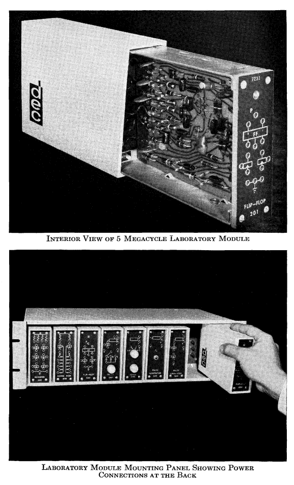
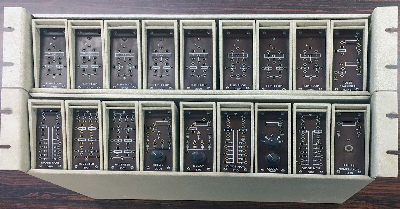
Packaging a tested circuit as a reusable block reduced the amount of transistor-level design required for each installation. Front-panel patching remained bulky, however, so the format suited laboratories better than processors containing hundreds of repeated logic functions.
From System Modules to FLIP CHIP #
System Building Blocks, later called System Modules, moved circuits onto compact cards with edge connectors. Cards plugged into sockets in a wire-wrapped backplane; the wrapped point-to-point wiring joined their pins into registers, counters, buses, and control paths. “Backplane” in this context means the connector field and its wiring, not a modern multilayer printed circuit board carrying a standardized bus.
FLIP CHIP packaging continued the card-and-backplane approach in a smaller form. DEC produced several electrically distinct series for logic, timing, and peripheral interfaces. Colored extraction handles and printed type numbers helped technicians locate a module, while maintenance documentation traced signals between module pins. The catalog unit might implement a few gates or one register bit, so a complete processor function emerged only after many copies were wired together:
- flip-flop modules retained the bits of a register;
- gate modules selected and combined register outputs;
- pulse and timing modules sequenced transfers;
- level converters and drivers connected the processor to memory and peripherals.
Modularity improved manufacturing and field repair because technicians could test
and replace a card. It did not make modules instruction-set components: an
ADD instruction depended on the combined datapath and control wiring across many
cards.
The PDP-1 as Architectural Context #
DEC announced the PDP-1 in 1959. Its 18-bit word, accumulator-centered design, core memory, and asynchronous peripheral interfaces established context for later 18-bit PDP systems. A standard memory held 4,096 words and used 12-bit addresses. A memory-reference instruction contained an operation code, an indirect-address bit, and a 12-bit address; operate and I/O instructions encoded control functions instead of a normal memory address.
The principal programmer-visible state included an 18-bit accumulator, an 18-bit I/O register, a program counter, and status or control flags. Paper tape, a console typewriter, and the Type 30 precision display were characteristic peripherals. Interactive graphics programs such as Spacewar! demonstrated why DEC’s comparatively accessible, interactive machine differed from batch-oriented computer use, although a PDP-1 still occupied several equipment racks.
PDP-7 Words, Instructions, and Memory #
DEC introduced the PDP-7 in 1964 as another 18-bit machine. Its basic coincident- current core memory held 4,096 words with a 1.75 µs cycle and could be expanded. The processor used one’s-complement arithmetic and an accumulator plus a one-bit link for arithmetic and shifting.
Important internal registers documented by DEC included:
| Register | Width | Purpose |
|---|---|---|
AC | 18 bits | Arithmetic and logical accumulator |
L | 1 bit | Link used by arithmetic and shift operations |
MB | 18 bits | Word moving to or from memory |
MA | 13 bits | Address presented to the basic memory system |
PC | 13 bits | Address of the next instruction |
IR | 4 bits | Major instruction operation code |
A memory-reference word assigns four bits to the major operation, one bit to
indirection, and thirteen bits to the address field. Memory extension hardware
provided access beyond the directly selected field. The instruction repertoire also
included IOT words for peripheral operations and microprogrammed OPR words in
which selected bits enabled compatible processor functions. Consequently, not every
18-bit pattern divides into an opcode and memory address in the same way.
Instruction execution proceeded through fetch and execute cycles implemented by module timing chains. For an indirect reference, the processor first fetched an effective address. For a memory operation, the memory address and buffer registers then mediated the core-memory cycle. The architecture exposed enough of those phases on its console and maintenance interfaces to support hardware diagnosis.
I/O without Memory-Mapped Registers #
PDP-7 peripherals communicated through the machine’s I/O system rather than through
ordinary memory-mapped device registers. An IOT instruction selected a device and
issued pulses whose interpretation belonged to that interface. Program flags and
interrupt facilities allowed software to wait for or respond to completion.
A base installation supported paper-tape and teleprinter equipment. Optional controllers connected displays, magnetic tape, and other devices. Device speed and protocol therefore depended on the attached controller; the 18-bit processor word did not imply that every peripheral transferred 18 useful bits at once.
The PDP-7 and Early Unix #
Bell Labs acquired a PDP-7 for other research, and Ken Thompson used the otherwise underutilized machine in 1969 to implement the first Unix system. Thompson had first written the Space Travel program on Multics and then adapted it to the PDP-7. Filesystem experiments, an assembler, a shell, and a small set of utilities grew into an operating system. Dennis Ritchie and other Bell Labs researchers joined the work.
Early Unix was written in PDP-7 assembly and was constrained by the machine’s small core memory. The better-known transition to C occurred after the project moved to the PDP-11. The PDP-7 relationship is thus a code-origin fact, not evidence that later Unix retained the PDP-7 instruction set or module organization.
Comments
Read or comment on GitHub (sign-in required to comment)